| Firestik
IBA-5 indoor base antenna |
 |
Summary |
|
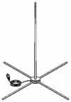
| The
complete assembly stands just over 5 feet (1.5m) tall.
Each kit includes a 'bare-hands tunable tip' antenna,
partially pre-assembled base hub assembly,
four 30" (76cm) radials, 18 feet (5.5m) of RG-58A/U Fire-Flex
coax cable and extra tuning screws. More info and instructions
for setting the SWR (IBA-5) |
All
about the IBA-5
The IBA-5 Indoor CB Antenna was introduced to the market in
1989. This product was an upgrade to the original antenna (IMB-5)
that Firestik introduced in 1977.
The Firestik indoor antenna was designed for two basic reason:
(1) to allow CB radio operation where outside antennas are not
allowed or, (2) for the CB'er who does not want to put up an outside
antenna. In either case, the operator should be aware that this
type of antenna is normally a compromise between rules, space and
optimum performance. In most cases the performance will not match
that of a good outdoor antenna. However, in many instances, the
indoor antenna by virtue of its elevation, as well as the scattering
effect the building has on its radiating field, has been known
to out perform antennas of equal design on a vehicle at street
level. Excellent performance can be recognized in spite of absorption
by various building materials. DX’ing (long range communications)
may not always be possible but is certainly a reality.
Indoor convenience is not without its limitations, and some compromise. An awareness
of possible restraining conditions (e.g. building design, construction materials
etc.) under which the antenna will be expected to perform can be appreciated
more for an intuitive approach rather than an endless list of do's and don’ts.
With respect to indoor base antennas, the Firestik Indoor Base Antenna has gained
a reputation for unexcelled performance. You should not let its limitations deter
you from using it. When you are in a situation that limits your choices down
to indoor antennas, be confident that the Firestik Indoor Base Antenna will satisfy
or surpass most persons expectations of how it should work. Keep in mind that
it was specifically designed to work indoors.
MECHANICAL DISCUSSION
The radiating element is a five-foot Firestik II type antenna with
our patented tunable tip mechanism. The core is 3/8" fiberglass wound with 19ga double
insulated magnet-wire. The antenna base is made of chrome plated 1/2" hex
brass stock and has standard 3/8"-24 threads. The assembly is covered with
white PVC shrink tubing.
The hub is a centrally located assembly that allows the antenna,
coax and radials to be connected together. It is made up of two
2" circular metal disks,
one upper and one lower. The upper disk has the coax and antenna coupling nut
attached and the lower disk is used to connect the four ground plane radials.
The disks are mounted directly above each other with 3/4" stand-offs.
The coaxial cable supplied with the kit is 18ft (5.5m) RG-58A/U.
This is high quality, stranded center conductor coax with average
shielding in the 95% plus range. A standard PL-259 connector is
installed on one end of the coax for connection to the radio. The
antenna end of the coax has our exclusive Fire-Ring connector for
trouble free operation.
The ground plane for the IBA-5 is supplied by four (4) 1" (25mm) x 30" (76cm)
flat steel radials. The radials are covered with black PVC shrink tubing and
have a protective vinyl tip on the outbound end. At the hub end of the radial,
a small hole is placed in order to secure the radials to the hub assembly.
LIMITATIONS
Unfortunately, indoor antennas will not, and can not be expected
to radiate energy at high radio frequencies through all metal buildings.
Buildings of all steel construction (top and sides), resting on
earth or concrete slabs, can be expected to reflect virtually all
incoming and outgoing transmitted energy without penetration. Buildings
with steel siding resting on earth, but with wood frame roofs that
are covered with wood shingles, composition or tar paper will allow
radiation, but largely upwards. Some outwards radiation from the
effects of scattering of the radio frequency field will depend
on roof shape and height above the sheet metal siding.
Aluminum mobile homes will act like the steel buildings mentioned
above. The difference, if any, will be in thin grade aluminum,
where in addition to reflection, some absorption and re-radiation
may occur, but direct penetration will be reduced.
Other limitations can occur in buildings where penetration and
range is otherwise excellent under dry conditions. Reduction of
radiated power will result from saturated wetting of the structures
top and sides due to rainfall and heavy dampness. Under these conditions,
limited range can be expected. Buildings constructed of concrete
and steel, concrete block, cinder block or red brick will all appear
earthy wet and will severely restrain radio transmissions. Otherwise
dry, a large amount of scattering can be expected due to the combined
effect of reduced penetration, absorption and re-radiation resulting
in an unpredictable radiation pattern. Local horizontal distance
may very well be restricted, yet, skip range expanded.
COMPROMISES
The five-foot antenna works as well as can be expected against
the non-resonant radio ground plane comprising four 30-inch ground
plane stabilizers. The ground plane stabilizers are made relatively
short deliberately for ease of assembly and placement around any
room, corner, furniture or even a closet or attic. The ground effect
(apparent length) of the short radials is therefore affected by
proximity to earth ground, electrical wiring or metal beams immediately
beneath the aligned radials.
Concrete slabs represent good earth ground surfaces at CB band
frequencies. The ground effect is diminished on wood frame ground
level floors over high crawl spaces, and more so over basement
areas. Ground effect is further diminished on wood flooring at
second story levels and higher, except where as stated above, when
placement happens to be in alignment immediately over electrical
wiring or metal beams.
While an exterior mast mounted ground plane or dipole antenna is
able to radiate into free space, the indoor antenna is surrounded
by obstructions that tend to interfere with its ability to be tuned.
An area should be chosen where it best works from the standpoint
of SWR. When a spot is selected and the antenna is finally tuned
in that spot, it should be left there. The area within 2 or 3 feet
of the antenna should remain unchanged once it is tuned. Invasion
of the near radiation field will de-tune the antenna unless it
was specifically tuned with the obstruction at that point.
The performance and ability to tune the antenna will be best if
the antenna can be located away from interfering objects. Undesirable
conditions can be greatly reduced if near field objects are only
on one side and at least 4 inches away from the antenna at the
base, 8 inches away at one foot up, 12 inches away at two feet
up and so on. The closer to the top of the antenna, the more critical
is the proximity of other objects since the antenna design creates
maximum radiation at the top loaded section.
Tuning the antenna for the lowest possible SWR is accomplished
in the same manner as on a vehicle. Surroundings and ground plane
area may not permit a SWR dip as low as that achievable on a vehicle
or a resonant ground plane. Measurements reportedly have been as
low as 1.2:1, however, 2.0:1 is by all means tolerable. At 2.0:1
SWR, the power loss is approximately 11%, which is less than 1/2
db.
TUNING AIDS WHERE DIFFICULTY IS ENCOUNTERED
The most common tuning problem with the IBA-5 shows up as high
and relatively flat SWR. That is, even when finish tuning the antenna,
the SWR at mid band (channel 19) is fairly high (1.7 to 2.5 range)
and doesn't change much across the entire band. This condition
is almost always caused by ground plane deficiency. In most cases
this can be corrected by making the antenna electrically longer
by changing the tuning screw on top of the antenna to a longer
length (aside from the standard tuning screw, we supply an extra
2" and 3" screw in the package).
If you have reached the upper maximum using the basic tuning screw, remove the
vinyl cap and the tuning screw. Transfer the knurled lock nut and o-ring to the
next longer screw and retune the antenna. The vinyl tip is optional, but remember
if you tune the antenna with the tip off then put in on afterwards, the SWR will
most likely change. If you want to use the tip and the longer screw, make an "x" cut
in the top of the cap and run the screw through it.
Properly assembled and tuned on a ground level slab floor, the
IBA-5 should show well under 1.5:1 SWR at the dip point (normally
channel 20). On elevated floors where the SWR dip may remain insidiously
high, indicating the antenna/ground plane network is quite reactive,
the coax cable can become a part of the network and may contain
standing waves, or a fractional part thereof. The coaxial reactance,
or part thereof, may be eliminated by folding one to three feet
of the coax back on itself in an S form. If a problem is still
Present, try a smaller or greater amount of cable in the double-back
process, and do it in a different place along the cable itself
until you find the combination which offers the lowest SWR. This
technique may sometimes be improved by adding RG-58/U type coax
to the existing length, totaling 24 feet from the mount center
and increasing the double-back length.
If problems persist, set the whole assembly on a sheet or blanket.
While an associate is keying up and advising on change of SWR readings,
slide the entire assembly to another location. Stop at the location
where SWR appears lowest and carefully revolve the blanket and
IBA-5 assembly (no more than 1/4 turn) to detect any perceptible
SWR improvement. Remove the blanket and fine-tune the antenna at
its best location. Keep your distance from the antenna during the
sliding around process.
ODDS AND ENDS
For those who like to scheme a little, a 16 to 118 foot length
of wire or flat braid in a squared off Z form, obscured under a
loose carpet, should work well to improve ground effect on upper
level wood floors. Dress and tape opposing ends of wire to opposite
corners of the room. Align one of the sets of radials directly
over the center section of wire and fine tune the antenna in that
location. If you use this method to increase your ground plane
area then care should be taken if you are running high-powered
radio equipment (linear amplifiers). High power directly relates
to heat dissipation. If the wire cannot easily release heat generated
by the power, the wires, in the additional ground plane, can become
hot. The higher the power, the more heat! Keep that in mind.
Another process that can greatly increase the efficiency of the
IBA-5, when set up in an attic, is the use of a spider-web ground
plane. Using ordinary wire (coated or uncoated), create a web of
wires running outward from the center hub. All ends at the hub
assembly need to be connected to the bottom (ground) disc of the
hub assembly.
OUTDOOR USE
Some of the mobile CB’ers also report excellent results from
using the IBA-5 out of doors. It works great when placed upon the
roof of a motor home or travel trailer at your favorite camp site.
Hunters have used it in their base camp to communicate with those
using handheld or mobile radio’s while away
from the camp in their CB equipped truck or ATV. The IBA-5 disassembles quickly
for easy storage.
|

